In the previous post we talked about Scaling out our newly deployed vIDM Deployment using vRealize Suite Lifecycle Manager. In this post we will take you through the process of Enabling Multi-Tenancy in vRealize Automation 8 Deployment.
Before we start with Enabling Multi-Tenancy ensure that you have generated and applied VMware Identity Manager and vRealize Automation Certificates using the process shared in the previous post Part-3: Scale-Out VMware Identity Manager Deployment.
The following steps in this final Blog of this Blog series will help us in Enabling Multi-Tenancy and will create 2 tenants for vRealize Automation 8.X Deployment:
1. Before we begin ensure that you have taken snapshot of all the Appliances and you have added your Active Directory under Directory Management in vRealize Suite Lifecycle Manager.
2. We can enable Multi-Tenancy under Tenant Management section of Identity and Tenant Management in vRealize Suite Lifecycle Manager:
vRealize Suite Lifecycle Manager – My Services Screen
3. We will observe a page with 4 recommendations to ensure an easy and error free tenancy experience. Click on ENABLE TENANCY.
Enable Tenancy – Tenant Management Screen
3. Ensure that you have taken Snapshots for all the Appliances and Trigger an Inventory Sync before clicking on Proceed.
4. On the next screen we will have to supply the name of our default tenant which is tenant in our case and click on ENABLE TENANCY.
Enable Tenancy – Master Tenant Screen
5. The request will go through 6 steps including the Step 6 of Initialize vRealize Automation cluster which Stops and Starts vRealize Automation services.
Enable Tenancy – Request Details Screen
6. Once we have successfully Enabled Tenancy, we can go back to Tenant Management in Identity and Tenant Management to ADD TENANT.
Add Tenant – Tenant Management Screen
7. Input the Tenant Name as tenant1 and supply the rest of the details for your tenant.
Add Tenant – Tenant Details Screen
8. We can copy the Directory from our Default tenant to the new tenant by supplying the Bind DN and Password or Copy the Directory to new tenant later on. For LCM to copy a Directory to a new tenant, the Directory has to be mapped to the Default tenant.
Add Tenant – Directory Details Screen
9. Select your vRA Environment. There is a reminder there on this screen to ensure that you have created the Certificates and have applied them to vRA Environment.
Add Tenant – Select Environment Screen
10. Run the Precheck and ensure that status reports Successful on completion.
Add Tenant – Run Precheck Screen
11. Review the details on the Summary screen and click CREATE TENANT.
12. The process of creating a new Tenant takes around 2 mins and after successful creation of new Tenant we can see our new Tenant listed under Tenant Management in Identity and Tenant Management section of vRealize Suite Lifecycle Manager.
Tenant Management – Tenant List Screen
With that we have come to the end of this 4 Blog series of Deploying and Configuring a Clustered vRealize Automation 8 Environment which is Highly-Available, Clustered, Distributed & Production ready with the capability of Multi-Tenancy.
In the previous post we talked about Deploying vRSLCM, vRA and vIDM Appliances using Easy Installer. In this post we will take you through the process of Expanding VMware Identity Manager Deployment from a Single-Node to a 3-Node Environment.
Before we start expanding VMware Identity Manager Deployment we need to generate Certificates for vRealize Automation and VMware Identity Manager Appliances. We will be generating SAN Certificates in this post using vRealize Suite Lifecycle Manager but you can also apply Custom CA Signed certificates by Importing the Certificates in vRealize Suite Lifecycle Manager.
The following steps will help in generating and applying the new Certificates with the help of vRealize Suite Lifecycle Manager:
1. We can find the existing Certificates and Generate new Certificates under Locker > Certificates section in vRLSCM:
vRealize Suite Lifecycle Manager Certificates
2. If you want to use Custom CA Certificates, you can click on Generate CSR and fill the details and send it to your CA for generating the Certificates but in this post we will be using the Generate option to Generate SSL Certificates using vRSLCM. Click on Generate and fill in the following details for vIDM Certificate:
Name: MyCloud-vIDM Certificate Common Name (CN): vidm Organization (O): MyCloud Organization Unit (OU): Delhi Country Code (C): IN Locality (L): Delhi State (ST): Delhi Key Length: 2048 Server/Domain/Hostname: vidm1.mycloud.lab, vidm2.mycloud.lab, vidm3.mycloud.lab, vidm.mycloud.lab, tenant.mycloud.lab, tenant1.mycloud.lab IP Address: 192.168.10.17, 192.168.10.18, 192.168.10.19, 192.168.10.16, 192.168.10.22
Generating new Certificate using vRSLCM
3. We need to Generate another Certificate for vRA Appliances:
Name: MyCloud-vRA Certificate Common Name (CN): vra Organization (O): MyCloud Organization Unit (OU): Delhi Country Code (C): IN Locality (L): Delhi State (ST): Delhi Key Length: 2048 Server/Domain/Hostname: vra.mycloud.lab, vra1.mycloud.lab, vra2.mycloud.lab, vra3.mycloud.lab, tenant1.vra.mycloud.lab IP Address: 192.168.10.12, 192.168.10.13, 192.168.10.14, 192.168.10.15
Note: If you are not very concerned about the certificates and would like to use a wildcard certificate, you can simply generate a wildcard certificate *.mycloud.lab
4. Once we have generated the Certificates, we will have to Import the MyCloud-vIDM Certificate in NSX-LB. We mentioned this Step as the last Step in Part-1: Configure Load Balancer for vRA 8 and vIDM of this Blog Series.
Import vIDM Certificate to NSX-LB
4. We will login to vRealize Suite Lifecycle Manager, under Lifecycle Operations section we need to go to globalenvironment & MyCloud-VRA8 Environment. Select Replace Certificate and apply the respective Certificates to each solution.
Replace vIDM and vRA Environment Certificates
5. Once we have successfully applied the newly Generated Certificates, we will proceed with the Actual Task at hand which is to expand our VMware Identity Manager Deployment from 1-Node to 3-Node which will make our environment truly Production Ready and Highly-Available. Now we need to go into globalenvironment under Environments and click on Add Components.
Adding Secondary Nodes to vIDM Environment
6. Please ensure that you have taken snapshots of your vIDM and vRA Appliances before proceeding, Trigger Inventory Sync, check the Checkbox which ensures that VMware Identity Manager cluster is Healthy and click Proceed.
Snapshot and vIDM Health Warning Screen
7. In Infrastructure section Select the Target vCenter Server, Cluster, Folder, Network and Datastore where you would like to Host the Secondary VMware Identity Manager Appliances. You can also enable Thin Disk Mode for the Storage of these Appliances.
Target Infrastructure for Secondary vIDM Nodes
8. Network Section should already have the details of Default Gateway, Netmask, Domain Name, Domain Search Path and DNS Servers.
9. Under Configuration section click on + next to Components and Select VMware Identity Manager Secondary Node. Repeat the process to add another Secondary Node to VMware Identity Manager Deployment and fill in the following details:
Cluster VIP FQDN: vidm.mycloud.lab Database IP Address: 192.168.10.20 VIDM3 VM Name: VIDM3 VIDM3 FQDN: vidm3.mycloud.lab VIDM3 IP Address: 192.168.10.19 VIDM2 VM Name: VIDM2 VIDM2 FQDN: vidm2.mycloud.lab VIDM2 IPAddress: 192.168.10.18
Cluster and Secondary Node IP Details for vIDM
10. Click on RUN PRECHECK and System will run multiple tests against the Entered Data, Infrastructure and VMware Identity Manager Configuration.
Run Precheck ScreenRe-Run Precheck and Download Report Screen
11. Once all Pre-Checks have Passed, Review all the details on Summary screen and click Submit.
Scale-Out Identity Manager Request Summary Screen
12. Once you click Submit, vRSLCM goes through Stages 1 to 16 for Expanding VMware Identity Manager Deployment from 1-Node to 3-Nodes.
vIDM Scale-Out Task Screen
The entire process of Expanding VMware Identity Manager Deployment took us around 1 hour and 45 mins on a Production Grade Hardware right from Generating new Certificates to Deploying and Configuring Secondary VMware Identity Manager Nodes. In the next and final part of this Blog series Part-4: Enable Multi-Tenancy for vRealize Automation 8 Deployment, we will discuss the process of Enabling Multi-Tenancy for your newly Deployed vRealize Automation 8 setup.
Nutanix Cloud Infrastructure is the Hyperconverged Infrastructure which brings together the Virtual Compute, Storage and Networking of the physical nodes into a single resource pool of the cluster which can consumed by applications hosted on top of it.
Hyperconverged Infrastructure brings the power of simplicity by providing a single console to manage your computer, storage and networking. HCI also enables Enterprises to manage their Infrastructure and utilise their Resources more efficiently.
Components of Nutanix Cloud Infrastructure includes:
Acropolis Hypervisor (AHV): Acropolis Hypervisor is Nutanix’s Type-1 Hypervisor installed on Bare Metal on-prem Hosts or on the Bare Metal Instances of Public Clouds to deliver the Virtualization capabilities.
Acropolis Operating System (AOS): Acropolis Operating System (AOS) is the software which runs inside the Controller Nodes (CVM) of Nutanix and delivers the storage capabilities
Prism: Prism is the Management software which provides the capabilities of managing an individual cluster using Prism Element UI and the functionality of managing multiple clusters using Prism Central UI.
Flow Network Security (FNS): Flow Network Security is the Network Security stack which helps Enterprises to secure their network by enhancing Application security and protecting the user workload
Disaster Recovery: Nutanix Disaster Recovery which was formerly known as Leap delivers the Synchronous, NearSync and Asynchronous replication capabilities for the workload to protect from site failures
Lifecycle Manager (LCM): The capabilities of managing the updates and upgrades of the Hyperconverged Infrastructure & for the HW Firmware is delivered using Lifecycle Manager.
Nutanix Kubernetes Enginer (NKE): Nutanix Kubernetes Engine is a kubernetes Management Platform which provides the capabilities of provisioning Kubernetes upstream conformant clusters and to manage the lifecycle of these K8s clusters.
Nutanix Unified Storage (NUS): Nutanix Unifies Storage is responsible for providing highly scalable enterprise level unified storage platform which can deliver Block, File and Object Storage.
Nutanix Cloud Infrastructure has its own SKU of Software Licenses which can be applied to the Nutanix environment with respective editions to leverage the above mentioned features.
In the upcoming blogs we’ll talk about each of these Nutanix Cloud Infrastructure (NCI) components in greater details along with demos. Happy Learning!
Nutanix is one of the leaders in cloud software which helps their customers in building Hybrid Multi-Cloud. Nutanix was founded in the year 2009 and as per the latest public data available, Nutanix is serving around 25000 customers across the globe.
Nutanix is based on Hyperconverged Infrastructure Technology which delivers services like virtualisation, software defined storage, software defined networking, security, database management and Kubernetes Management.
In this series of Blogs we’ll cover some of the key features and functionalities offered by Nutanix Cloud Platform. On a High level, Nutanix Cloud Platform Comprises of two components: Nutanix Cloud Infrastructure and Nutanix Cloud Platform. Nutanix Cloud Platform delivers Hybrid Multi-Cloud capabilities through a unified Control Plane. We’ll talk about some of the key components of Nutanix Cloud Platform and we’ll also cover some of the How-To Blogs on Nutanix Platform. Stay Tuned!
In the previous post we talked about Configuring Load Balancer for vRealize Automation 8 and VMware Identity Manager in a NSX-V environment. In this post we will take you through the process of Deploying vRealize Lifecycle Manager, Clustered vRealize Automation Appliances and VMware Identity Manager appliance
Ensure that all DNS Records and IP Reservations are in place
Keep DNS server and NTP server details handy
Now we re ready to deploy to deploy our new appliances, the steps to deploy vRSLCM, vRA and vIDM appliances are as follows:
1. Mount the Easy Installer ISO and Launch installer.exe located under F:\vrlcm-ui-installer\win32\installer.exe
vRealize Easy Installer Launch Screen
2. Please go through the Introduction and Accept the End User License Agreement. Click Next
End User License Agreement Screen
3. Enter the Appliance Deployment Target details like vCenter Server Hostname, Administrator Username and Password.
Appliance Deployment Target Screen
4. Select a Target Location, Target Cluster and Datastore.
Select a Target Location ScreenSelect a Target Compute Resource ScreenSelect a Destination Storage Location Screen
6. Enter the details of Network Configuration which includes Target Network, IP Assignment Type, Subnet Mask, Default Gateway, DNS Servers, Domain Name and NTP Servers.
Network: DC_MGMT_VLAN100 IP Assignment: static Subnet Mask: 255.255.255.0 Default Gateway: 192.168.10.1 DNS Servers: 192.168.10.50, 192.168.10.51 Domain Name: mycloud.lab Provide NTP Server for the appliance: 192.168.10.70,192.168.10.71
Network Configuration Screen
7. Enter your Password. This password will be used for vRSLCM admin & root account, vRA root account, vIDM admin, sshuser, root user and default configuration user.
Password Configuration Screen
8. Enter Virtual Machine name, IP Address, FQDN, Datacenter Name and vCenter Name for vRealize Suite Lifecycle Manager. Set Increase Disk Size in GB to 20 and Leave FIPS Mode Compliance to deafult.
Virtual Machine Name: VRSLCM IP Address: 192.168.10.11 Hostname: vrslcm.mycloud.lab Data Center Name: MYCLOD-DC vCenter Name: MYCLOUD-VC Increase Disk Size in GB: 20 FIPS Mode Compliance: Enabled
Lifecycle Manager Appliance Configuration Screen
9. In Identity Manager Configuration, we will initially configure a Single Node VMware Identity Manager deployment which will be expanded to a clustered deployment in next blog in this series. Select Install New VMware Identity Manager and Enter the details of Virtual Machine Name, IP Address, FQDN, Default Configuration Admin, E-mail Address and Node size as per your environment’s requirement. Tick Sync Group Members to the Directory When Adding Group checkbox.
Virtual Machine Name: VIDM1 IP Address: 192.168.10.17 Hostname: vidm1.mycloud.lab Default Configuration Admin: configadmin Default Configuration Email: configadmin@vsphere.local Node Size: Medium Sync Group Members to the Directory When Adding Group: Enabled
Identity Manager Appliance Configuration Screen
10 a. Under vRealize Automation Configuration section select Clustered Deployment. Enter vRealize Automation Environment Name, License Key, Turn Off FIPS Compliance Mode and Select the Node size.
vRA Environment Name: MYCLOUD-VRA8 License Key: XXXXX-XXXXX-XXXXX-XXXXX-XXXXX FIPS Compliance Mode: Disabled Node Size: Medium
10 b. Enter vRealize Automation Load Balancer IP Address, Load Balancer FQDN and leave SSL terminated at Load-Balancer unchecked. In the vRealize Automation Primary Node Details section, enter Virtual Machine Name, IP Address and FQDN for the vRA Primary Node.
10 c. Enter vRealize Automation Secondary Node-1 and Secondary Node-2 Details, Virtual Machine Name, IP Address and FQDN. Leave Advanced Configuration for vRealize Automation to default.
vRealize Automation Node Details: Primary Node Virtual Machine Name: VRA1 IP Address: 192.168.10.13 Hostname: vra1.mycloud.lab Secondary Node-1 Virtual Machine Name: VRA2 IP Address: 192.168.10.14 Hostname: vra2.mycloud.lab Secondary Node-2 Virtual Machine Name: VRA3 IP Address: 192.168.10.15 Hostname: vra3.mycloud.lab Internal Pods and Services Configuration: Use Default
vRealize Automation Configuration – Secondary Node-1 and Secondary Node-2 Details
11. Review Configuration details on the Summary screen and click Submit.
vRealize Easy Installer Summary Screen
12. Installation Process goes through 5 stages: Initializing, Installing vRSLCM, Moving Binaries, Initiating install vIDM and vRA and Finish vRA Install.
Installation Process Screen
13. Once the Installation Process has passed the stage of vRSLCM Installation, we can login to vRSLCM UI using the username as admin@local and Password which we entered during the Password Configuration stage.
Installation Process – vRSLCM Services Started Screen
14. In vRealize Suite Lifecycle Manager select Lifecycle Operations under My Services and then to the Requests section. You’ll find 2 requests: globalenvironment – Create Environment (IDM Installation) and MYCLOUD-VRA8 – Create Environment (vRA Installation).
vRealize Suite Lifecycle Manager – My Services Screen
15. VMware Identity Manager Installation Request goes through 8 Stages before your vIDM deployment is ready.
16. vRealize Automation Installation Request goes through 13 Stages before your vRealize Automation Deployment is setup and ready to use. Our vRealize Automation Installation failed twice during the setup process but the process was intelligent enough to provide intuitive insights into error and to allow us to resume from failed stage.
MYCLOUD-VRA8 – Create Environment Screen
The entire Deployment and Setup process took us around 1 hour and 35 mins and we were using Enterprise Grade Hardware for this setup. In the next part of this series Part-3: Scale-Out VMware Identity Manager Deployment, we will discuss the process of Expanding vIDM Environment by Adding Two Secondary Nodes.
In this series of blog posts we will talk about the steps involved in deploying a Clustered Production-Ready vRealize Automation Environment enabled with Multi-Tenancy. We have divided this series into 4 blog posts which will be as follows:
In this post we are going to talk about one of the Primary requirement to deploy a clustered vRealize Automation deployment with Multi-Tenancy, which is, Setting up your Load Balancer. We are using NSX-V for our setup but you can use NSX-T, F-5 or Citrix Netscaler. We are assuming that you already have your Active Directory and DNS configured.
Before we begin setting up our Load Balancer we need to perform the following pre-requisites:
We need 11 IP Addresses and 12 DNS entries.
vRSLCM (A-Type Record) – 1 IP Address and DNS Record vrslcm.mycloud.lab – 192.168.10.11
vRA- 3 IP Addresses for vRA Appliances and 1 vRA-LB IP with DNS Records vra.mycloud.lab (A-Type Record) – 192.168.10.12 (vRA LB IP Address) vra1.mycloud.lab (A-Type Record) – 192.168.10.13 vra2.mycloud.lab (A-Type Record) – 192.168.10.14 vra3.mycloud.lab (A-Type Record) – 192.168.10.15
vIDM – 3 IP Addresses for vIDM Appliances and 1 vIDM-LB IP with DNS Records We will also need 1 IP Address for vIDM Postgres replication vidm.mycloud.lab (A-Type Record) – 192.168.10.16 (vIDM LB IP Address) vidm1.mycloud.lab (A-Type Record) – 192.168.10.17 vidm2.mycloud.lab (A-Type Record) – 192.168.10.18 vidm3.mycloud.lab (A-Type Record) – 192.168.10.19 Internal vIDM Postgres IP Address – 192.168.10.20
Load Balancer Interface IP Address – 192.168.10.21
DNS Entry for Default Tenant tenant.mycloud.lab (A-Type Record) – 192.168.10.16 tenant1.mycloud.lab (A-Type Record) – 192.168.10.16
Multi-Tenancy DNS Entries: tenant1.vra.mycloud.lab (CNAME Record) – vra.mycloud.lab
Now we re ready to configure our Load Balancer in NSX-V, the steps to configure NSX-V LB are as follows:
1. Deploy a new NSX-V Edge Services Gateway with High Availability.
6. Enter the Name for the Interface, Select the Port Group and enter the Primary and Secondary IP Addresses. Primary IP Address should be your Load Balancer Interface IP and Secondary IP Addresses should be the Load Balancer IPs for your vRA & vIDM.
4. Create 2 Service Monitors, One for vRealize Automation and one for VMware Identity Manager.Create 2 Service Monitors, One for vRealize Automation and one for VMware Identity Manager.
vRealize Automation Service Monitor: Name: vRealize Automation8 Interval: 3 Timeout: 10 Max Retries: 3 Type: HTTP Expected: 200 Method: GET URL: /health
NSX Edge – Service Monitor for vRealize Automation Screen
VMware Identity Manager Service Monitor: Name: VMware Identity Manager Interval: 3 Timeout: 10 Max Retries: 3 Type: HTTPS Expected: 200 Method: GET URL: /SAAS/API/1.0/REST/system/health/heartbeat
NSX Edge – Service Monitor for VMware Identity Manager Screen
5. Now we will create 2 Pools of Member Servers, One for vRealize Automation and one for VMware Identity Manager.
NSX Edge – Pool Configuration for vRealize Automation Screen
vRealize Automation Pool Members: Members: vra1, vra2 and vra3 IP Addresses: 192.168.10.13, 192.168.10.14 and 192.168.10.15 Monitor Port: 8008 Port: 443
NSX Edge – vRealize Automation Pool Members Screen
NSX Edge – VMware Identity Manager Pool Configuration Screen
VMware Identity Manager Pool Members: Members: vidm1, vidm2 and vidm3 IP Addresses: 192.168.10.17, 192.168.10.18 and 192.168.10.19 Monitor Port: 443 Port: 443
NSX Edge – VMware Identity Manager Pool Members Screen
6. The last step in the process of setting up our Load Balancer is to create 2 Virtual Servers, again one for vRealize Automation and one for VMware Identity Manager.
In Part-2 of this Blog post series Part-2: Deploy vRSLCM, vRA and vIDM Appliances using Easy Installer, we will discuss the process to deploy vRealize Suite Lifecycle Manager 8, vRealize Automation 8 and VMware Identity Manager Appliances using Easy Installer. Stay Tuned.
In this post we are sharing a PowerCLI script that we used to export a list of LUNs attached to ESXi hosts in a cluster along with the details of Path Selection Policy selected for the LUN and CommandsToSwitchPath parameter set for the LUNs.
Just replace the vCenter_Server_IP_Address/FQDN, Cluster_Name and Path of CSV File and run the script to generate a report of LUNs mapped to all ESXi hosts in a vSphere cluster in your environment. BOOM!!
In vRealize Automation 8 the process of creating an Event Subscription has changed a little bit. In vRealize Automation 8 there are 40 Event Topics already defined under Extensibility Library in Cloud Assembly.
Event topics which you can choose from while creating an Event Subscription vRealize Automation are as follows:
Blueprint configuration EventLog Blueprint version configuration Kubernetes cluster allocation Compute allocation Kubernetes cluster post provision Compute post provision Kubernetes cluster post removal Compute post removal Kubernetes cluster provision Compute provision Kubernetes cluster removal Compute removal Load balancer post provision Compute reservation Load balancer post removal Deployment action completed Load balancer provision Deployment action requested Load balancer removal Deployment completed Network Configure Deployment onboarded Network post provisioning Deployment requested Network post removal Deployment resource action completed Network provisioning Deployment resource action requested Network removal Deployment resource completed Project Lifecycle Event Topic Deployment resource requested Security group post provision Disk allocation Security group post removal Disk post Removal Security group provision Disk post resize Security group removal
In order to understand an Event topic review the Descripton, Topic ID, Blocakble and Schema of the Event Topic.
Compute provision Event Topic
If you want to create a Subscription for an Event Topic, just select the Event Topic and click on Subscribe, select the ABX Action or Workflow to trigger, select the Blocking of events and Subscription scope. Schema of an Event Topic can also be reviewed on this screen, Schema (Payload in the previous versions of vRealize Automation) of an Event Topic is a set of Properties which will be passed to Orchestrator when an event of this Topic is triggered.
Test Subscription for Compute provision Event Topic
Important Tip: If you are not sure about the Schema of an Event Topic, create a Blank Workflow with Input Variable of name “inputProperties” & Type “Properties” and Create a Test Subscription using this Blank Workflow. Name of the Input Variable is Important here, if you name it something else it will not receive the Properties from Cloud Assembly.
Schema Properties received by the Orchestrator Workflow
Did you notice that the Workflow ran twice? This is because i have Specified 2 Machine components in the Blueprint and the Workflow ran each time a Machine Component was provisioned for this Deployment request.
2 Workflow Runs for the Test Subscription
The names of the machine components in the Test Blueprint used for this illustration are “Primary_VM” and “Secondary_VM”.
Blueprint for which Event Subscription was triggered
There is one more important thing which you can specify while creating an Event Subscription using Event Topics, which is the Condition. Condition is something which you describe to filter out a specific Event from the list of Events which are triggered when a user requests for Services using Service Broker.
Condition to filter Events for an Event Topic
Condition can only be specified in Javascript Syntax in the current version of vRealize Automation. For Instance if I would like to trigger the same Test Workflow only for the Secondary_VM, i can specify a condition in the Test Subscription as event.data.blueprintId == ‘e9d2abc4-94fa-48f1-a1db-19a31510a375’ && event.data.componentId == ‘Secondary_VM’ Blueprint ID can be copied from one of the previous sample Workflow runs.
Sample Filter Condition for Events in Topic
This condition would ensure that the Workflow is triggered if the Blueprint requested has an id e9d2abc4-94fa-48f1-a1db-19a31510a375and only for the component with id Secondary_VM. If you request a Deployment now using the same Blueprint, the Workflow will be triggered only once and that is for the Machine Component Secondary_VM.
Single Workflow Run for Secondary_VM Machine Component
Note: I noticed one typo in the examples provided for Condition statement in vRealize Automation 8, there is a space missing after event.data.blueprintId == and the actual id. I had to spend 15 mins figuring out why the event is not triggering a workflow, so make sure that the Syntax for the Condition is correct.
Bad Syntax for the Condition Statement Example
With that you are now ready to create Event Subscription in vRealize Automation 8. Enjoy!!
In this blog we have covered the 2 methods of taking Backup of your VMware Aria Operations (vRealize Operations Manager) configuration.
VMware Aria Operations introduced a feature called Content Management in version 8.2 back in October 2020.
Content Management helps the Customers to Backup and Export their configuration of VMware Aria Operations which can be further used to restore the configuration like Dashboards, Views, Report Templates, Supremetrics and a lot more in case you run into issues with the deployment.
We have covered two methods of taking a Backup and Export of VMware Aria Operations Configuration – First one, using the Content Management Tab under Administration in VMware Aria Operations UI and Second one, using a Python Script which makes use of the native APIs of Aria Operations.
Python script which we have developed has been tested on Python 3.10.10 version and Aria Operations 8.10 version. This script can also be scheduled as a Scheduled Task to take periodic configuration backups.
Method -1: Content Management Tab under Administration in VMware Aria Operations UI
Method -2: Python Script which uses native APIs of Aria Operations
In vRealize Automation 8.X, Easy Installer deploys a vIDM appliance which is used for Authentication by vRealize Automation whether you choose a Standalone deployment or a Clustered deployment. As we already have an external vIDM appliance as part of our vRA 8.X deployment, we can use it for configuring Single Sign-On for VMware vRealize Suite products.
Single Sign-On configuration is supported in 7.X versions of vRealize Suite products as well but we need an external VMware Identity Manager which most of the customers do not deploy. vRealize Automation 7.X Appliances also include an embedded version of VMware Identity Manager, even though we can enable the UI for the embedded vIDM using the command vcac–vami horizon ui enable but there is no documentation suggesting that making changes directly to VMware Identity Manager is supported by VMware.
In this post we will discuss the process of configuring Single Sign-On for vRealize Suite 8.X version products. In this article I am assuming that an Active Directory domain has already been configured in VMware Identity Manager.
vRealize Automation:
1. Login to VMware Identity Manager and click on Web Apps under the Catalog section.
VMware Identity Manager Web Apps Section
2. Click on New to configure vRealize Automation Web Application Link.
Creating a New Web Application Link in Identity Manager
3. In the Name section enter vRealize Automation 8.X (vRA) and upload an Icon file for vRealize Automation.
vRealize Automation Web App Configuration
4. Leave the Category section blank and click Next.
5. In Authentication Type select Web Application Link and type https://vRA_FQDN/csp/gateway/portal/#/consumer in Target URL.
Target URL for vRealize Automation Web App
5. Click Next and then click Save.
6. Now the only task left is to assign this App to Active Directory users who already have access to vRealize Automation. Select the newly created Application and Click on Assign.
Assign vRealize Automation Web App to Users/Groups
5. Search the name of Users/User Groups to publish the App, select the Deployment type as Automatic and click Save.
Assign vRealize Automation Web App Enterprise Admins Group
6. Next time the user authenticates with vIDM and goes to User Portal, he/she will be able to see the newly published vRA 8.X Application.
Access VMware Identity Manager User Portal
7. Next time the user authenticates with vIDM and goes to User Portal, he/she will be able to see the newly published vRA 8.X Application.
Launch vRealize Automation Web App from vIDM Catalog
8. Once the user clicks on Open on this App, user will be authenticated & re-directed to vRealize Automation portal.
vRealize Log Insight:
1. Before publishing vRealize Log Insight as an App in VMware Identity Manager we need to configure vIDM as an Authentication Source in vRealize Log Insight and we need to obtain the Target URL.
2. Login to vRealize Log Insight. Click on Administration and Under Authentication enter the details of your vIDM.
Configure vRealize Log Insight to use VMware Identity Manager for Authentication
3. Provide access to VMware Identity Manager Users/User Groups in Administration section under Access Control > Users and Groups.
Access Control in vRealize Log Insight
4. In order to obtain the Target URL, logout from vRealize Log Insight & logout from vIDM and select System Domain.
5. Open vRealize Log Insight in a new Tab, select VMware Identity Manager from the Drop-down and click on Login via SSO.
vRealize Log Insight Target URL for VMware Identity Manager
Capture vRealize Log Insight Target URL for VMware Identity Manager
7. URL highlighted in red is our Target URL for vRealize Log Insight. Follow the same process as vRealize Automation App and publish vRealize Log Insight for users using the vRealize Log Insight Target URL.
8. Now the users should be able to launch vRealize Log Insight App from vIDM User Portal & Authenticate using vIDM Single Sign-On.
vRealize Operations Manager:
1. For vRealize Operations Manager we need to follow the process similar to vRealize Log Insight. Configure vIDM as Authentication Source, Grant permissions to vIDM Users/Groups in vROps & obtain the Target URL.
2. Login to vRealize Operations Manager as an Admin user. Click on Administration and Under Authentication Sources click Add. Select Source Type as VMware Identity Manager and enter the details of your vIDM Appliance.
Configure VMware Identity Manager as Authentication Source in vRealize Operations Manager
3. Provide access to VMware Identity Manager Users/Groups by Importing them in Administration section under Access > Access Control > User Accounts and User Groups.
Import Users/Groups from VMware Identity Manager for Access Control in vRealize Operations Manager
4. In order to obtain the Target URL, logout from vRealize Operations Manager & logout from vIDM and select System Domain.
5. Open vRealize Operations Manager in a new Tab, select VMware Identity Manager from the Drop-down and click REDIRECT.
vRealize Operations Manager Target URL for VMware Identity Manager
6. You’ll be redirected to VMware Identity Manager for login. Copy the URL from the Address Bar of the browser. URL will look something like:
8. Follow the same process as vRealize Automation App and publish vRealize Operations Manager App for users using the vRealize Operations Manager Target URL.
9. Now the users should be able to launch vRealize Operations Manager App from vIDM User Portal & Authenticate using vIDM Single Sign-On.
vRealize Suite Lifecycle Manager:
1. For vRealize Suite Lifecycle Manager the process is fairly easy. We just need to provide users access to vLCM under Identity and Tenant Management and publish the Target URL.
2. Login to vRealize Suite Lifecycle Manager as an Admin user. Click on dentity and Tenant Management.
Identity and Tenant Management in vRealize Suite Lifecycle Manager
3. In Directory Management section, click on Directories click Add Directory by selecting Active Directory over LDAP.
Add Active Directory in vRealize Suite Lifecycle Manager
4. The process of Adding the Active Directory is same as vRealize Automation 7.X.
Active Directory over LDAP configuration in vRealize Suite Lifecycle Manager
5. Once Active Directory has been configured, provide relevant permissions to Users/Groups under User Management section.
User Management in vRealize Suite Lifecycle Manager
6. Replace the details of the below URL with your environment details and you’ll get Target URL for vRealize Suite Lifecycle Manager.
http://lcm01.mydomain.lab/lcm/login/vidm
8. The process of publishing vRealize Suite Lifecycle Manager App for users using the vRealize Suite Lifecycle Manager Target URL remains the same.
Note: The current versions of vCenter Server do not support VMware Identity Manager as an Identity Provider. NSX-T does support Single Sign-On configuration using vIDM. For more details on integrating NSX-T with IDM, check out this blog.
The final catalog of your VMware Identity Manager will have Web Apps for all 4 vRealize Suite Components. Enjoy!!
VMware Identity Manager Signle Sign-On User Catalog
There was a requirement in one of the projects to assign Custom Attributes to multiple Virtual Machines hosted in a vSphere Environment. We wrote a PowerCLI script to Assign the Custom Attributes to Virtual Machines using a CSV file which had all the details of the Custom Attributes.
Just replace the vCenter_Server_IP_Address/FQDN and Path of CSV File and run the script to assign Custom Attributes to Virtual Machines in vSphere environment. BOOM!!
In this series of blogs we will cover the architectural components of VMware NSX.VMware NSX is a Software Defined Network Virtualization and Security solution offered by VMware to support Virtual Machine and cloud native applications in an on-premise as well as VMware’s cloud hosted on hyperscaler environment.
VMware NSX provides complete set of Networking services like Routing, Switching, Firewalling, Loadbalancing and QoS. In this blog of VMware NSX we will cover NSX Architecture Components and in the following blogs we will talk about all these services in detail.
A typical Production NSX deployment comprises of NSX Manager Appliances and Transport Nodes. There are Planes which run across these 2 type of Nodes which are as follows:
Management Plane: Management Plane resides inside the NSX Manager Appliances. Management Plane is responsible for storing the desired configuration inside a database which is replicated across the 3 NSX Manager Appliances which run as 3 Virtual Machines.
Management Plane also acts as a User Interface as well as the entry point for the programmatic users.
Control Plane: Control Plane resides inside a NSX Controller element which also resides inside the NSX Manager Appliances with the latest releases of NSX. In the earlier releases of NSX, NSX Controllers used to reside inside separate Virtual Machines. Control Plane is responsible for pushing the configuration entered by the user using UI or APIs to the Data Plane.
Management Plane and Control Plane are bundled in a virtual machine called NSX Manager Appliance. NSX Manager Appliance is clustered into 3 Appliances for Production deployments to ensure High Availability.
Data Plane: Data Plane is responsible for performing stateless packet forwarding and the user data passes through the Data Plane. Data Plane comprises of Transport Nodes which can be an ESXi Host, Edge VM or a Bare Metal Server. KVM hosts were supported in the earlier NSX releases however with the latest release of NSX, KVM Hosts are no longer supported as a Transport Node.
Transport Nodes: A Transport Node is a Node which is prepared for NSX, runs the local control plane daemon and forwarding engines implementing NSX Data plane. A Transport Node can be an Edge VM, ESXi Host or a Bare Metal Server.
Edge Transport Node: NSX Edge Transport nodes are service appliances dedicated to running centralized network services that cannot be distributed to the hypervisors like North/South routing, load balancing, DHCP, VPN, NAT, etc. They can be instantiated as a bare metal appliance or in virtual machine form factor. They are grouped in one or several clusters. Each cluster is representing a pool of capacity.
Host Transport Node: Host Transport Nodes are ESXi Hypervisors which runs the distributed Network services. NSX used to support KVM as well as a Host Transport Node but in the latest releases support for KVM as a Host Transport Node has been withdrawn.
In the next blog, we will talk about the Distributed Routing in VMware NSX.
I hope this blog was informative for you, stay tuned for our upcoming blogs. Happy Learning!!
In vRealize Automation 8 the process of creating an Event Subscription has changed a little bit. In vRealize Automation 8 there are 40 Event Topics already defined under Extensibility Library in Cloud Assembly.
Event topics which you can choose from while creating an Event Subscription vRealize Automation are as follows:
Blueprint configuration EventLog Blueprint version configuration Kubernetes cluster allocation Compute allocation Kubernetes cluster post provision Compute post provision Kubernetes cluster post removal Compute post removal Kubernetes cluster provision Compute provision Kubernetes cluster removal Compute removal Load balancer post provision Compute reservation Load balancer post removal Deployment action completed Load balancer provision Deployment action requested Load balancer removal Deployment completed Network Configure Deployment onboarded Network post provisioning Deployment requested Network post removal Deployment resource action completed Network provisioning Deployment resource action requested Network removal Deployment resource completed Project Lifecycle Event Topic Deployment resource requested Security group post provision Disk allocation Security group post removal Disk post Removal Security group provision Disk post resize Security group removal
In order to understand an Event topic review the Descripton, Topic ID, Blocakble and Schema of the Event Topic.
Compute provision Event Topic
If you want to create a Subscription for an Event Topic, just select the Event Topic and click on Subscribe, select the ABX Action or Workflow to trigger, select the Blocking of events and Subscription scope. Schema of an Event Topic can also be reviewed on this screen, Schema (Payload in the previous versions of vRealize Automation) of an Event Topic is a set of Properties which will be passed to Orchestrator when an event of this Topic is triggered.
Test Subscription for Compute provision Event Topic
Important Tip: If you are not sure about the Schema of an Event Topic, create a Blank Workflow with Input Variable of name “inputProperties” & Type “Properties” and Create a Test Subscription using this Blank Workflow. Name of the Input Variable is Important here, if you name it something else it will not receive the Properties from Cloud Assembly.
Schema Properties received by the Orchestrator Workflow
Did you notice that the Workflow ran twice? This is because i have Specified 2 Machine components in the Blueprint and the Workflow ran each time a Machine Component was provisioned for this Deployment request.
2 Workflow Runs for the Test Subscription
The names of the machine components in the Test Blueprint used for this illustration are “Primary_VM” and “Secondary_VM”.
Blueprint for which Event Subscription was triggered
There is one more important thing which you can specify while creating an Event Subscription using Event Topics, which is the Condition. Condition is something which you describe to filter out a specific Event from the list of Events which are triggered when a user requests for Services using Service Broker.
Condition to filter Events for an Event Topic
Condition can only be specified in Javascript Syntax in the current version of vRealize Automation. For Instance if I would like to trigger the same Test Workflow only for the Secondary_VM, i can specify a condition in the Test Subscription as event.data.blueprintId == ‘e9d2abc4-94fa-48f1-a1db-19a31510a375’ && event.data.componentId == ‘Secondary_VM’ Blueprint ID can be copied from one of the previous sample Workflow runs.
Sample Filter Condition for Events in Topic
This condition would ensure that the Workflow is triggered if the Blueprint requested has an id e9d2abc4-94fa-48f1-a1db-19a31510a375and only for the component with id Secondary_VM. If you request a Deployment now using the same Blueprint, the Workflow will be triggered only once and that is for the Machine Component Secondary_VM.
Single Workflow Run for Secondary_VM Machine Component
Note: I noticed one typo in the examples provided for Condition statement in vRealize Automation 8, there is a space missing after event.data.blueprintId == and the actual id. I had to spend 15 mins figuring out why the event is not triggering a workflow, so make sure that the Syntax for the Condition is correct.
Bad Syntax for the Condition Statement Example
With that you are now ready to create Event Subscription in vRealize Automation 8. Enjoy!!
In this blog we have covered the 2 methods of taking Backup of your VMware Aria Operations (vRealize Operations Manager) configuration.
VMware Aria Operations introduced a feature called Content Management in version 8.2 back in October 2020.
Content Management helps the Customers to Backup and Export their configuration of VMware Aria Operations which can be further used to restore the configuration like Dashboards, Views, Report Templates, Supremetrics and a lot more in case you run into issues with the deployment.
We have covered two methods of taking a Backup and Export of VMware Aria Operations Configuration – First one, using the Content Management Tab under Administration in VMware Aria Operations UI and Second one, using a Python Script which makes use of the native APIs of Aria Operations.
Python script which we have developed has been tested on Python 3.10.10 version and Aria Operations 8.10 version. This script can also be scheduled as a Scheduled Task to take periodic configuration backups.
Method -1: Content Management Tab under Administration in VMware Aria Operations UI
Method -2: Python Script which uses native APIs of Aria Operations
In this blog we have covered the manual process of creating a custom Virtual Private Cloud (VPC) on Amazon Web Services (AWS) cloud platform.
We have also talked about some of the key concepts related to VPC like Route Table, Subnet, Network Access Control List (ACL) and Security Group.
A Virtual Private Cloud (VPC) is a virtual, private and logically isolated network that an AWS Customer can define which is dedicated for that Customer.
VPC enable Customers to launch their resources like EC2 (Virtual Machine) instances in this private network.
Key Concepts:
Route Table – A Route Table is a set of rules called routes which helps router make effective decisions in routing packets.
Subnets – A subnet is a range of IP Addresses present in a CIDR block in which you can launch your EC2 instances
Network Access Control List – Network ACL includes inbound and outbound rules which allows traffic to flow in and out of a Subnet.
Security Group – Security Groups consist of rules which are associated with Resources and controls the traffic entering or leaving a resource.
For the detailed process of creating a custom Virtual Private Cloud on AWS, please watch our video.
Create Your First VPC on AWS
I hope this blog was informative for you, stay tuned for our upcoming blogs. Happy Learning!!
There was a requirement in one of the projects to create multiple (approx. 60) datastores using a PowerCLI script. We wrote a PowerCLI script to perform this operation on multiple LUNs presented to all ESXi hosts in the cluster.
Just replace the vCenter_Server_IP_Address/FQDN, Path of File Containing Datastore Names, NAA Ids, ESXi Host, Cluster Name and Sleep Interval after each Datastore creation operation with the details of your environment. BOOM!!
There was a requirement in one of the projects to export permissions assigned to each Virtual Machine hosted in a vSphere Environment. We wrote a PowerCLI script to fetch the list of users along with the Role assigned to each user and export these details to a CSV file.
Just replace the vCenter_Server_IP_Address/FQDN and Path of CSV File and run the script to export VI Permissions assigned to each Virtual Machine in vSphere environment. BOOM!!
In vRealize Automation 8.X, Easy Installer deploys a vIDM appliance which is used for Authentication by vRealize Automation whether you choose a Standalone deployment or a Clustered deployment. As we already have an external vIDM appliance as part of our vRA 8.X deployment, we can use it for configuring Single Sign-On for VMware vRealize Suite products.
Single Sign-On configuration is supported in 7.X versions of vRealize Suite products as well but we need an external VMware Identity Manager which most of the customers do not deploy. vRealize Automation 7.X Appliances also include an embedded version of VMware Identity Manager, even though we can enable the UI for the embedded vIDM using the command vcac–vami horizon ui enable but there is no documentation suggesting that making changes directly to VMware Identity Manager is supported by VMware.
In this post we will discuss the process of configuring Single Sign-On for vRealize Suite 8.X version products. In this article I am assuming that an Active Directory domain has already been configured in VMware Identity Manager.
vRealize Automation:
1. Login to VMware Identity Manager and click on Web Apps under the Catalog section.
VMware Identity Manager Web Apps Section
2. Click on New to configure vRealize Automation Web Application Link.
Creating a New Web Application Link in Identity Manager
3. In the Name section enter vRealize Automation 8.X (vRA) and upload an Icon file for vRealize Automation.
vRealize Automation Web App Configuration
4. Leave the Category section blank and click Next.
5. In Authentication Type select Web Application Link and type https://vRA_FQDN/csp/gateway/portal/#/consumer in Target URL.
Target URL for vRealize Automation Web App
5. Click Next and then click Save.
6. Now the only task left is to assign this App to Active Directory users who already have access to vRealize Automation. Select the newly created Application and Click on Assign.
Assign vRealize Automation Web App to Users/Groups
5. Search the name of Users/User Groups to publish the App, select the Deployment type as Automatic and click Save.
Assign vRealize Automation Web App Enterprise Admins Group
6. Next time the user authenticates with vIDM and goes to User Portal, he/she will be able to see the newly published vRA 8.X Application.
Access VMware Identity Manager User Portal
7. Next time the user authenticates with vIDM and goes to User Portal, he/she will be able to see the newly published vRA 8.X Application.
Launch vRealize Automation Web App from vIDM Catalog
8. Once the user clicks on Open on this App, user will be authenticated & re-directed to vRealize Automation portal.
vRealize Log Insight:
1. Before publishing vRealize Log Insight as an App in VMware Identity Manager we need to configure vIDM as an Authentication Source in vRealize Log Insight and we need to obtain the Target URL.
2. Login to vRealize Log Insight. Click on Administration and Under Authentication enter the details of your vIDM.
Configure vRealize Log Insight to use VMware Identity Manager for Authentication
3. Provide access to VMware Identity Manager Users/User Groups in Administration section under Access Control > Users and Groups.
Access Control in vRealize Log Insight
4. In order to obtain the Target URL, logout from vRealize Log Insight & logout from vIDM and select System Domain.
5. Open vRealize Log Insight in a new Tab, select VMware Identity Manager from the Drop-down and click on Login via SSO.
vRealize Log Insight Target URL for VMware Identity Manager
Capture vRealize Log Insight Target URL for VMware Identity Manager
7. URL highlighted in red is our Target URL for vRealize Log Insight. Follow the same process as vRealize Automation App and publish vRealize Log Insight for users using the vRealize Log Insight Target URL.
8. Now the users should be able to launch vRealize Log Insight App from vIDM User Portal & Authenticate using vIDM Single Sign-On.
vRealize Operations Manager:
1. For vRealize Operations Manager we need to follow the process similar to vRealize Log Insight. Configure vIDM as Authentication Source, Grant permissions to vIDM Users/Groups in vROps & obtain the Target URL.
2. Login to vRealize Operations Manager as an Admin user. Click on Administration and Under Authentication Sources click Add. Select Source Type as VMware Identity Manager and enter the details of your vIDM Appliance.
Configure VMware Identity Manager as Authentication Source in vRealize Operations Manager
3. Provide access to VMware Identity Manager Users/Groups by Importing them in Administration section under Access > Access Control > User Accounts and User Groups.
Import Users/Groups from VMware Identity Manager for Access Control in vRealize Operations Manager
4. In order to obtain the Target URL, logout from vRealize Operations Manager & logout from vIDM and select System Domain.
5. Open vRealize Operations Manager in a new Tab, select VMware Identity Manager from the Drop-down and click REDIRECT.
vRealize Operations Manager Target URL for VMware Identity Manager
6. You’ll be redirected to VMware Identity Manager for login. Copy the URL from the Address Bar of the browser. URL will look something like:
8. Follow the same process as vRealize Automation App and publish vRealize Operations Manager App for users using the vRealize Operations Manager Target URL.
9. Now the users should be able to launch vRealize Operations Manager App from vIDM User Portal & Authenticate using vIDM Single Sign-On.
vRealize Suite Lifecycle Manager:
1. For vRealize Suite Lifecycle Manager the process is fairly easy. We just need to provide users access to vLCM under Identity and Tenant Management and publish the Target URL.
2. Login to vRealize Suite Lifecycle Manager as an Admin user. Click on dentity and Tenant Management.
Identity and Tenant Management in vRealize Suite Lifecycle Manager
3. In Directory Management section, click on Directories click Add Directory by selecting Active Directory over LDAP.
Add Active Directory in vRealize Suite Lifecycle Manager
4. The process of Adding the Active Directory is same as vRealize Automation 7.X.
Active Directory over LDAP configuration in vRealize Suite Lifecycle Manager
5. Once Active Directory has been configured, provide relevant permissions to Users/Groups under User Management section.
User Management in vRealize Suite Lifecycle Manager
6. Replace the details of the below URL with your environment details and you’ll get Target URL for vRealize Suite Lifecycle Manager.
http://lcm01.mydomain.lab/lcm/login/vidm
8. The process of publishing vRealize Suite Lifecycle Manager App for users using the vRealize Suite Lifecycle Manager Target URL remains the same.
Note: The current versions of vCenter Server do not support VMware Identity Manager as an Identity Provider. NSX-T does support Single Sign-On configuration using vIDM. For more details on integrating NSX-T with IDM, check out this blog.
The final catalog of your VMware Identity Manager will have Web Apps for all 4 vRealize Suite Components. Enjoy!!
VMware Identity Manager Signle Sign-On User Catalog
In this post we are sharing a PowerCLI script that we used to export a list of LUNs attached to ESXi hosts in a cluster along with the details of Path Selection Policy selected for the LUN and CommandsToSwitchPath parameter set for the LUNs.
Just replace the vCenter_Server_IP_Address/FQDN, Cluster_Name and Path of CSV File and run the script to generate a report of LUNs mapped to all ESXi hosts in a vSphere cluster in your environment. BOOM!!
There was a requirement in one of the projects to assign Custom Attributes to multiple Virtual Machines hosted in a vSphere Environment. We wrote a PowerCLI script to Assign the Custom Attributes to Virtual Machines using a CSV file which had all the details of the Custom Attributes.
Just replace the vCenter_Server_IP_Address/FQDN and Path of CSV File and run the script to assign Custom Attributes to Virtual Machines in vSphere environment. BOOM!!
There was a requirement in one of the projects to export permissions assigned to each Virtual Machine hosted in a vSphere Environment. We wrote a PowerCLI script to fetch the list of users along with the Role assigned to each user and export these details to a CSV file.
Just replace the vCenter_Server_IP_Address/FQDN and Path of CSV File and run the script to export VI Permissions assigned to each Virtual Machine in vSphere environment. BOOM!!
There was a requirement in one of the projects to create multiple (approx. 60) datastores using a PowerCLI script. We wrote a PowerCLI script to perform this operation on multiple LUNs presented to all ESXi hosts in the cluster.
Just replace the vCenter_Server_IP_Address/FQDN, Path of File Containing Datastore Names, NAA Ids, ESXi Host, Cluster Name and Sleep Interval after each Datastore creation operation with the details of your environment. BOOM!!
We were working on a requirement last week to pull a report of all vRealize Automation Managed Machines using PowervRA Module version 3.7.0 which supports vRealize Automation 7.6. While generating the report using a PowerShell script we noticed that the output was only showing the name of the Machine owner instead of the ID.
Then we started digging into the function Get-vRAResource of PowervRA Module and we noticed that the method which is used by function Get-vRAResource in PowervRA Module is /catalog-service/api/consumer/resourceViews
vRealize Automation API Method used by function Get-vRAResource in PowervRA
After checking the vRealize Automation Catalog Service API 7.6 documentation we realized that this method was deprecated in vRealize Automation 7.5 version and this method is similar to /catalog-service/api/consumer/resources method.
Method /api/consumer/resourceViews has been deprecated since version 7.5
We used our Good Old API building Platform Postman to do a side by side comparison of vRA API methods /catalog-service/api/consumer/resourceViews and /catalog-service/api/consumer/resources. If you’ll look at the output of both the methods closely, you’ll notice that the resourceViews methods returns only the Name of the Owner where as the resources methods returns an Array which includes the values of tenantName, ref, type & value out of which ref is the Machine Owner’s ID.
Side-by-Side Comparison of API Methods /api/consumer/resourceViews and /api/consumer/resources using Postman
Armed with all that information we prepared our script to pull resource Information of all vRA Managed Machines using PowervRA function Get-vRAResource and then we used the vRealize Automation API method /catalog-service/api/consumer/resources/{ResourceID} to get the Machine Owner’s ID of each Resource to generate our vRA Managed VMs report with Owner’s ID.
In vRealize Automation 7.X VMware Identity Manager (vIDM) was embedded in vRealize Automation Appliance, even though the UI for vIDM is disabled however we can still use the capability of vRealize Automation to Authenticate using a RADIUS server. There is a very informative VMware blog on Configuring vRA 7 for 2 Factor Authentication posted by Jon Schulman back in February 2016 but a few things have changed since then.
I had to configure Two Factor Authentication for one the customers, this was when i realized that there are few modification which are required to configure Two-Factor Authentication in vRA. In order to provide a brief overview, we will be using a Ubuntu Machine to install and will install Google Authenticator and RADIUS server on this machine. Ubuntu machine will integrate with Active Directory for Authentication and then we will configure vRealize Automation to use RADIUSAuthAdapter to Authenticate users with “AD Password + Google Authenticator Passcode”.
Configuring Two-Factor Authentication:
Pre-requisites:
1. 1 Ubuntu 18.04.3 VM 2. VM should have minimum of 2 vCPUs and 4 GB RAM 3. Active Directory 4. vRealize Automation 7.X 5. DNS Record for Ubuntu Machine
1.Configure Ubuntu Machine:
I am using an Ubuntu VM of 2 vCPUs, 4 GB Memory and 20 GB HDD for this Demo.
Patch/Update the Ubuntu machine and Install open-vm-tools using the below commands:
Once the Power Broker Identity Services has been installed, there is one more thing that we need to do before we add Ubuntu machine to Active Directory. We need to uninstall Avahi daemon:
sudo apt-get remove avahi-daemon
Now we can add our Ubuntu machine to Active Directory using the below command:
Now we need to add the below mentioned lines to /usr/share/lightdm/lightdm.conf.d/50-ubuntu.conf file to allow users to login to Ubuntu machine using Active Directory Credentials on Ubuntu login screen: sudo nano /usr/share/lightdm/lightdm.conf.d/50-ubuntu.conf
allow-guest=false greeter-show-manual-login=true
Install Freeradius Server on your Ubuntu machine using the below command: sudo apt install freeradius
Edit the file /etc/freeradius/3.0/radiusd.conf and replace the below entries: Replace: user = freerad group = freerad
With: user = root group = root
Run the below command to enable PAM modules: ln -sf /etc/freeradius/3.0/mods-available/pam /etc/freeradius/3.0/mods-enabled/pam
Comment out all the lines in the file /etc/pam.d/radiusd and add the below lines: auth requisite pam_google_authenticator.so forward_pass account required pam_lsass.so use_first_pass
Add the below entry to the file /etc/freeradius/3.0/users:
DEFAULT Auth-Type := PAM
Modify the file /etc/freeradius/3.0/clients.conf to make an entry for vRealize Automation server in the Ubuntu machine:
Edit the file and uncomment pam to enable Pluggable Authentication Modules in file /etc/freeradius/3.0/sites-enabled/default:
Restart FREEARDIUS service:
2.Install Google Authenticator:
Once your machine has been setup to Authenticate using Active Directory, we will proceed with installing Google Authenticator and generate Google Authenticator Token to generate Passcodes using Google Authenticator Mobile Application:
Use the below command to install Google Authenticator:
sudo apt install libpam-google-authenticator
We can now begin enabling our Active Directory users to start enrolling for Google Authenticator Application on their Mobile phones. Advise the users to login to the respective App Stores (Google Playstore & Apple’s App Store) to download and Install Google Authenticator App.
Assume the Identity of the user you want to enable for login and run the command google-authenticator: su demo@vmlab.local google-authenticator
Type y to generate a time-based token and a QR Code and Secret Key will be generated for th user. User can scan the QR code using Google Authenticator App or User can enter the Secret Key to import the tokwn in the App:
There are 5 Emergency Scracth codes which are generated for the user to use when user wants to Authenticate but does not have Mobile phone handy with him/her. These codes are one-time codes and answer the below questions as per your environment. I would recommend answering the 3rd question as “yes”, as it will allow the users to use a token for upto 4 minutes otherwise the each token expires within 30 seconds.
Google Authenticator doesn’t allow you to take a screenshot of an actie token hence the image but a successfully imported token in Google Authenticator looks like this:
3.Configure vRealize Automation to Authenticate using Radius:
Login to vRealize Automation with Tenant Administrator credentials and click on the Connector under Directories Management section:
Click on the Auth Adapters and click on the RadiusAuthAdapter to enable Radius Authentication.
Enable Radius Adapter and enter the details of the Ubuntu machine, set the Authentication Type as PAP, you can enter Number of attemps to Radius server and Time out values as per your requirement and enter the shortname for your domain followed by a Backslash “\”:
If you want to enable High Availability, you can setup another Ubuntu machine in a similar fashion but for our demo we will not be enabling Secondary server. Click on Save to save the settings and enable the Radius Auth Adapter. Enter the Passphrase hint to provide users information about entering Password followed by Passphrase.
Click on Network Ranges and create a new Network range, All clients which are using the IP addresses of this range will be required to authenticate using Password + Passcode (Two-Factor Authentication). If you are using a Distributed vRealize Automation Deployment, Start and End IP Address of the Network Range should be the vRA Portal VIP:
Now the last step in the configuration is to setup a Policy Rule to enforce Radius Authentication. Create a Policy Rule by selecting the newly created Network Range, select All Device Types to access the content from and select the Authentication method as Radius and click on Ok.
Drag and drop the newly created Network Range to the top of the list and click Save to save the configuration:
Now when you’ll attempt to login to vRealize Automation portal using a client with the IP Address defined in the Network Range, you’ll prompted with the new Passphrase hint:
In order to login to vRA portal, enter your Password followed by the Google Authenticator Passphrase:
BOOM!!, you have managed to configure Two-Factor Authentication for vRealize Automation.
We received a request to export the details of vRealize Automation Network Profile’s IP Ranges. We wrote a PowerShell script which uses PowervRA (3.6.0) module to extract the details of Network Ranges for each Network Profile.
There was a requirement in one of the projects to perform an unattended shutdown of multiple Virtual Machines during a planned Maintenance Window. We wrote a PowerCLI script to perform shutdown operation on multiple VMs with a delay of 20 seconds between each shutdown.
foreach ($VM in $VMs) { Get-VM $VM | Select Name, PowerState | Ft -AutoSize -Wrap } Disconnect-VIServer -Confirm:$false
Note: Virtual Machines are shutdown gracefully and requires VMware Tools to installed on machine.
Just replace the vCenter_Server_IP_Address/FQDN, Path of File Containing VMs Name and Sleep Interval after each shutdown operation with the details of your environment. BOOM!!
In order to execute PowerShell scripts from vRealize Orchestrator, we need to configure a PowerShell host as an endpoint for your vRealize Orchestrator. vRealize Orchestrator which comes embedded with vRealize Automation appliance already has PowerShell Plug-in installed and has all the required workflows available under Library > PowerShell.
Adding PowerShell host to vRealize Orchestrator:
Pre-requisites:
vRealize Orchestrator with PowerShell Plug-in
Windows Host – 2 vCPUs & 4 GB RAM, PowerShell PSVersion 5.X, Windows Server 2012 or later (Domain-joined)
Certificate for Windows Host (if you are using Custom certificates)
Active Directory User Account – Service Account which should be part of Administrators and Remote Management Users groups on Windows Host.
Configuration Steps:
Enable PowerShell Remoting on Windows Host by running the command Enable-PSRemoting command. The Enable-PSRemoting cmdlet configures the computer to receive PowerShell remote commands that are sent by using the WS-Management technology. PowerShell remoting is enabled by default on Windows Server 2012. You can use Enable-PSRemoting to enable PowerShell remoting on other supported versions of Windows and to re-enable remoting on Windows Server 2012 if it becomes disabled. This command has to be run only once on the Windows PowerShell Host. Increase the amount of memory each PowerShell session is allowed to consume for executing the scripts by running the below command:
winrm set winrm/config/winrs @{MaxMemoryPerShellMB=”2048″}
Import the Custom Certificate generated by your Certificate Authority to your Windows PowerShell Host. In this example, we are generating a Self-signed certificate (Using a Self-signed certificate is not recommended for the Production environment). Self-Signed certificate can be generated using the below command:
Copy this newly generated Self-signed certificate to Console Root > Certificates > Trusted Root Certification Authorities > Certificates. Note down the thumbprint of the certificate from the Certificate details:
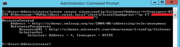
Create a WinRM HTTPS Listener by running the below mentioned command:
Replace PWShellHost_FQDN with the FQDN of your PowerShell Host and replace Certificate_Thumbprint with the thumbprint of the Self-signed certificate generated in the previous step.
Run the following command to enable Kerberos authentication for WinRM service:
winrm set winrm/config/service/auth @{Kerberos=”true”}
If you need to delete the WinRM HTTPS Listener for some reason, run the below command:
Create an Inbound Windows Firewall Rule on Windows PowerShell Host by running the below command:
New-NetFirewallRule –Direction Inbound –Action Allow –DisplayName “Windows Remote Management [HTTPS-In]” –Description “Inbound rule for Windows Remote Management via WS-Management. [TCP 5986]” –Program “System” –Profile Domain,Private –Protocol TCP –LocalPort “5986” –RemotePort Any
Firewall Rule Details:
Name: Windows Remote Management (HTTPS-In) Description: Inbound rule for Windows Remote Management via WS-Management. [TCP 5986] Program: System Local IP address: Any Remote IP address: Any Direction: Inbound Profile: Domain, Private Protocol: TCP Local port: 5986 Remote port: Any
We need to configure vRealize Orchestrator to use Kerberos Authentication. Edit the krb5.conf configuration file on your vRealize Orchestrator server located at path /usr/java/jre-vmware/lib/security/ to specify the domain name and domain controller name. If the file does not already exist, create a new file and paste the contents after modifying as per your requirement in the file:
Set the permissions of the file krb5.conf to chmod 7777.
Run vRealize Orchestrator workflow Import a certificate from URL located under Library > Configuration > SSL Trust Manager > Import a certificate from URL to import the certificate of the PowerShell Host to vRealize Orchestrator: There will be couple of warnings thrown at you, just accept all the warnings and verify the Certificate Validity and accept to Import the certificate.
Once the Certificate has been imported successfully, you’ll be able to see the certificate under the CA Keystore:
Next step is to run the vRO workflow Add a PowerShell Host located under Library > PowerShell > Configuration > Add a PowerShell host workflow to add the Windows PowerShell Host to vRO.
Enter PowerShell Host FQDN under Host, Any reference name under Name and Port should be 5986 for HTTPS connection: Select WinRM under PowerShell remote host type, HTTPS under Transport protocol, set Accept all certificates to Yes and Authentication type should be Kerberos. Enter the credentials of Active Directory Service Account which is part of the Administrators and Remote Management Users groups on Windows PowerShell host and select Session mode as Shared Session. Under Advanced Settings select Shell Code Page as UTF8. Once Workflow has ran successfully, you’ll be able to see the newly configured PowerShell host under PowerShell plugin in Inventory tab of vRealize Orchestrator.
Now comes the part we have been waiting for, we can now execute any PowerShell script hosted on this newly configured Windows PowerShell Host. To execute a PowerShell Script we will run the vRealize Orchestrator workflow Invoke an external script located under Library > PowerShell > Invoke an external script. Select your newly configured Windows PowerShell host under the Host. Enter the path of the PowerShell script which is hosted on the Windows PowerShell Host and enter any arguments under Arguments section. Voila! You are now all set to run all your favorite PowerShell scripts using vRealize Orchestrator.